Plugin User Guides
Plugin Interface Overview
Includes general information pertaining to the interfaces of MixWave plugins.
Updated 2 days ago
This article is a general overview of the global features included in MixWave amp, pedal and mixing plugins.
General GUI Usage
The Graphic User Interface (GUI) features an assortment of knobs and switches where some resemble physical analog hardware with added functionality. Hovering over knobs, sliders, or switches will reveal its current value.
Knobs
To turn a knob clockwise, click on the control with your mouse and move the cursor up. To turn the knob counter-clockwise, click on the control with your mouse and move the cursor down.
Double click the control to reset the knob to its default value. To fine-adjust a knob value, hold down the Command key (macOS) or the Control key (Windows) while dragging the control with the mouse cursor.
Switches
Simply click on the button or switch to interact with these controls. Certain switches may have LED indicators to signal that the parameter is engaged or disengaged.
Amp Plugin Global Features
Amp Plugin Layout
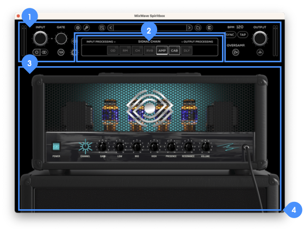
Utility Controls - Contains all the global controls for the plugin, presets, and version number information.
Signal Chain - Input and output processing controls and the rearrangeable Signal Chain of all the effects/devices included in the plugin.
Device Section - By default, the amp will initially be displayed here. Depending on which component is selected in the Signal Chain will display the interface for the currently selected module or device.
Resize Button - Click and drag to resize the plugin window.
Amp Plugin Utility Controls
For all MixWave amp plugins, the top set of controls features the following.

Input Meter - Displays the input level on the meter bars ranging from -INF dB, with half way representing around -6 dB, a full bar indicating 0 dB, and a peak exceeding 0 dB.
Input Volume Knob - Sets the input level of your signal.
Gate Knob - Sets the threshold of the noise gate.
Settings Button - Opens the panel for audio settings (standalone only) and window size preferences.
Tuner Button - Shows or hides the Tuner interface.
Preset Selection Menu - Selects a preset. The name of active preset will be displayed and an asterisk (*) symbol will appear when the active preset has been modified.
About Button - Opens the “About” panel containing software version information and a button to open the User Guide.
Output Volume Knob - Controls the overall output volume from the plugin.
Output Meter - Displays the output level on the meter bars ranging from -INF dB, with half way representing around -6 dB, a full bar indicating 0 dB, and a peak exceeding 0 dB.
Mono/Stereo Input Button - Click to choose between mono and stereo inputs.
Gate On/Off Switch - Enables or disables the noise gate.
Transpose - Shifts the signal up or down in pitch by a constant interval (+12/-12 semitones)
Certain amp plugins may not include this feature.Transpose Bypass* - Enables or disables the transpose.
Oversampling Button - This engages or disengages the oversampling. This increases the internal sampling, reducing aliasing and artifacts, at the cost of higher CPU usage.
Output Limiter Bypass - Enables or disables the output limiter.
BPM Controls - With the Sync button ON, the global tempo of the plugin will sync to the BPM of the host. Turn the Sync button OFF to manually set the tempo by typing in the BPM or clicking the Tap button.
Tuner

Tuner Mute - Mutes the plugin output signal.
Tuner Display - Shows the tuning and accuracy of the pitch. Tune your instrument until the needle sits on the center.
Tuning Pitch: Sets center tuning frequency.
Close Button - Close tuner window.
Signal Chain

Input Processing Button - Click to show or hide the input processing controls.
Signal Chain Button - If the Input or Output Processing panels are open, click to reveal the Signal Chain Display.
Signal Chain Display - This displays all available modules and devices, in the order of signal flow, from left to right. Drag and drop each Module Button to rearrange the order of the Signal Chain. Click on any Module Button to reveal its controls in the Device Section below. Double click any Module Button to engage or bypass. A white frame around a box is an indicator that the module is on, while a gray frame box indicates the module is bypassed/off. A bold line at the bottom of the frame indicates which module is currently being viewed in the Graphic User Interface (GUI).
Output Processing Button - Click to show or hide the output processing controls.
Input & Output Processing
On the left and right sides of the Signal Chain section, there are identical sets of EQ and compressor controls to apply on the signal input and output.
Equalizer
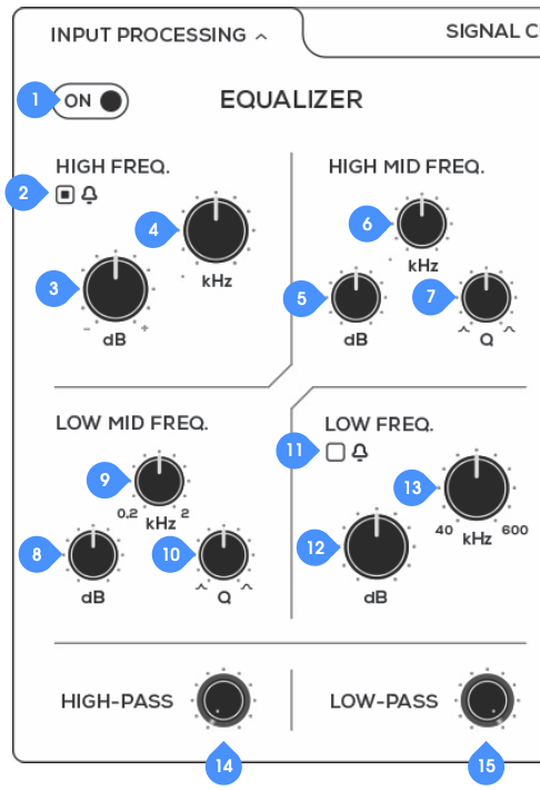
EQ On/Bypass - Turns the Equalizer on or bypassed.
High Frequency Switch - Switches the high frequency EQ band from shelf to bell.
High Frequency Gain Knob - Boost or cut the high frequency.
High Frequency Knob - Adjusts the frequency of the High Frequency section.
High Mid Frequency Gain - Boost or cut the High Mid Freq Section frequency
High Mid Frequency Knob - Adjusts the frequency of the High Mid Frequency section.
High Mid Q Knob - Changes the shape / Q value of the High Mid Frequency Section.
Low Mid Frequency Gain - Boost or cut the Low Mid Frequency.
Low Mid Frequency Knob - Adjusts the frequency of the Low Mid Frequency section.
Low Mid Q Knob - Changes the shape / Q value of the High Mid Frequency Section.
Low Frequency Switch - Switches the low frequency EQ band from shelf to bell.
Low Frequency Gain - Boost or cut the Low Frequency.
Low Frequency Knob - Adjusts the frequency of the Low Frequency Section.
High Pass Knob - Sets the center frequency of the high pass filter.
Low Pass Knob - Sets the center frequency of the high pass filter.
Compressor
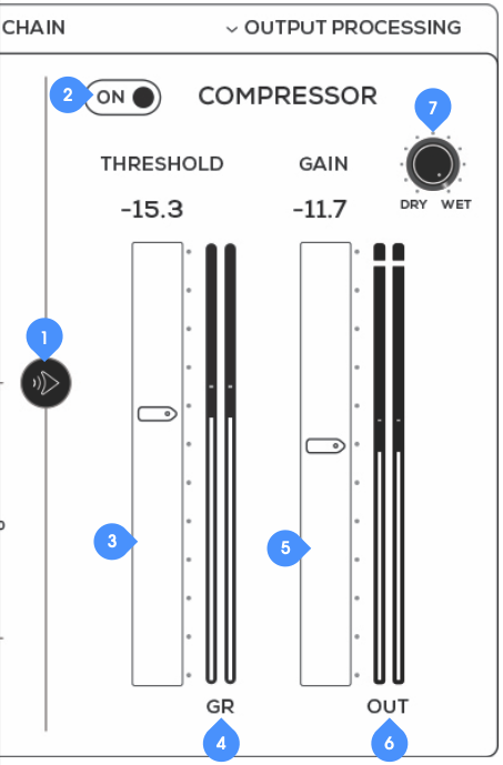
EQ/Compressor Swap - Flips the order of the EQ and Compressor.
EQ ON/Bypass - Turns the Compressor on or bypassed.
Threshold Fader - Adjusts the level at which compression begins.
Threshold Meter - Displays the compressor threshold.
Gain Fader - Controls the output level/limiter.
Gain Meter - Displays the compressor gain.
Dry/Wet Knob - Blends the levels of the “dry” (clean) and the “wet” (processed) signal from the compressor.
Speakers & Cabinets
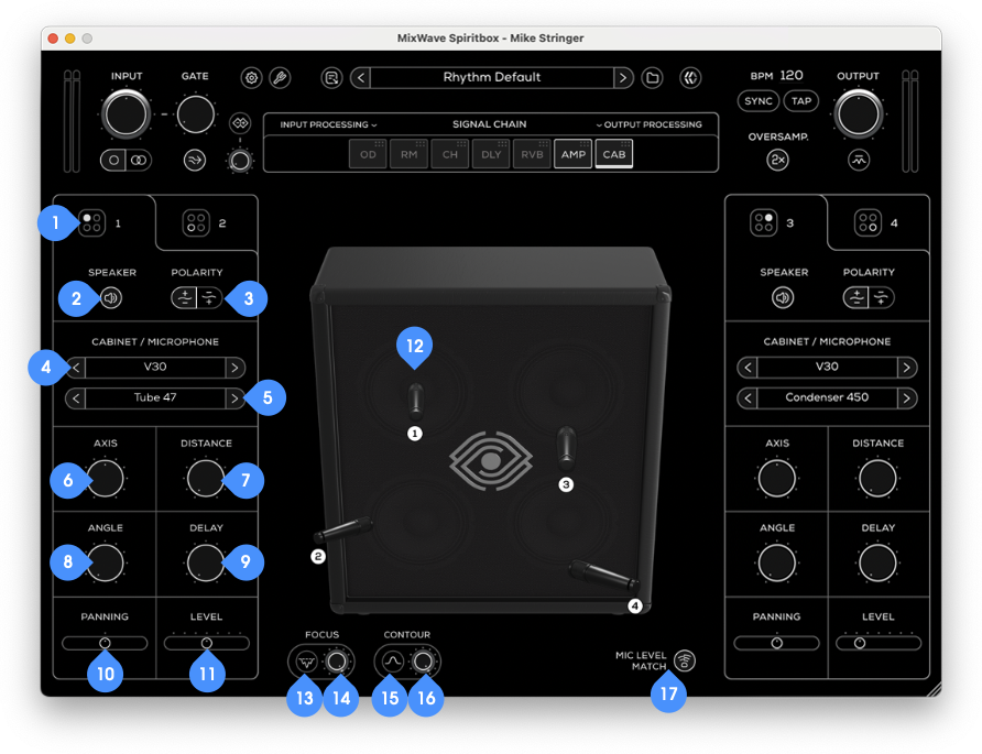
Cabinet Selection Tab - Switch between selections for top and bottom speaker on either cabinet.
Cabinet On/Off Button - Engages or disengages the selected cabinet.
Phase Switch - Allows you to toggle the polarity of the signal.
Cabinet Selector - Click through to select between speaker cabinets.
Microphone Selector - Click through to select between microphone options.
Axis Knob - Adjust the microphone placement horizontally, from speaker center to speaker edge.
Distance Knob - Adjust microphone distance.
Angle Knob - Adjust the microphone angle.
Phase Delay Knob - Add or subtract the delay time of the cabinet impulse response. Maximum time is 1 ms.
Cabinet Panning Slider - Adjust the panning position of the corresponding cabinet. This parameter is only shown in stereo mode.
Cabinet Volume Slider - Adjust the volume of the selected cabinet. This parameter is only shown in stereo mode.
Microphone Position - This indicates the position of each microphone. Click and drag any microphone to adjust its position, and reset it center by double-clicking the microphone.
Focus Button - Removed harsh frequencies when engaged.
Focus Mix Knob - Blends the “dry” (clean) input signal and the “wet” (processed) signal from the Focus button.
Contour Button* - Adds a subtle fixed EQ when engaged.
Contour Mix Knob - Blends the “dry” (clean) input signal and the “wet” (processed) signal from the Contour button.
Microphone Level Match Button - Clicking this switch will automatically match the volume levels between the cabinets when used in stereo.
Audio Settings (Standalone Only)
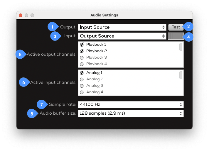
Output - Select an output from the available outputs on your computer. If you are using an interface and external speakers, it is recommend to select your interface as the output. Otherwise, select another output such as your computer speakers or headphone output.
Test Button - Plays a test tone through the selected output when clicked.
Input - Select an input from the available inputs on your computer. If you are using an interface, it is recommend to select your interface as the input source. Otherwise, select any other available input source your instrument is connected to.
Input Test Meter - Will display any incoming signal from the selected input.
Active Output Channels - Displays a list of available outputs depending on the I/O connected to your computer. Select any channel to set the output channels for the plugin. Most interfaces or configurations commonly use output channels 1 and 2 as their main outputs.
Active Input Channels - Displays a list of available inputs depending on the I/O connected to your computer. Select any channel to set the input channel for the plugin.
Sample Rate - Set the plugin sample rate to 44.1 Hz, 48 Hz, 88.2 Hz, 96 Hz, 176.4 Hz, or 192 Hz. When changing the sample rate, make sure that your interface and/or computer is also set to the same sample rate setting otherwise a sample rate mismatch may cause audio output issues.
Audio Buffer Size - Sets the buffer size from 32 samples (0.7 ms) to 2048 samples (46.4 ms). Lower buffer sizes will have less latency while higher buffer sizes will have more latency.
Pedal Plugin Global Features
Pedal Plugin Layout
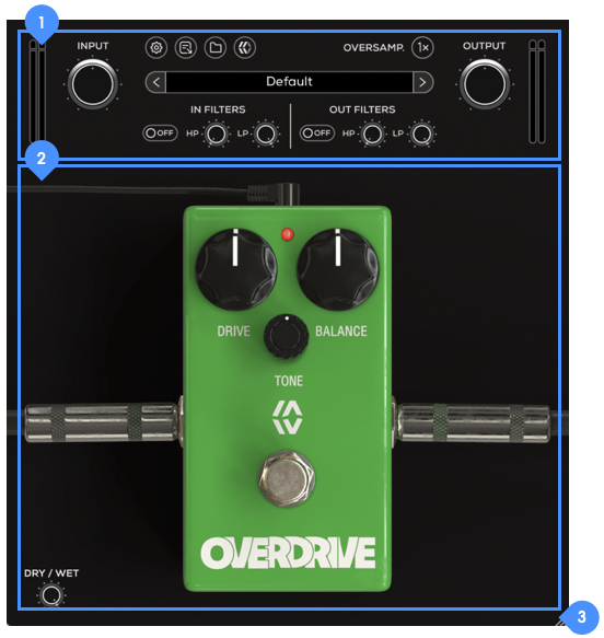
Utility Controls - Contains all the global controls for the plugin, presets, and version number information.
Device Section - Displays the user interface of the device.
Resize Button - Click and drag to resize the plugin window.
Pedal Plugin Utility Controls

Input Meter - Displays the input level on the meter bars.
Input Volume Knob - Sets the input level of your signal.
Settings Button - Opens the panel for window size preferences.
About Button - Opens the “About” panel containing software version information and a button to open the User Guide.
Preset Selection Menu - Selects a preset. The name of active preset will be displayed and an asterisk (*) symbol will appear when the active preset has been modified.
Oversampling Button - This engages or disengages the oversampling. This increases the internal sampling, reducing aliasing and artifacts, at the cost of higher CPU usage.
Output Volume Knob - Controls the overall output volume from the plugin.
Output Meter - This displays the output level on the meter bars.
Input Filter Bypass - Enables or disables the input filters.
Input High Pass Knob - Sets the center frequency of the input high pass filter.
Input Low Pass Knob - Sets the center frequency of the input low pass filter.
Output Filter Bypass - Enables or disables the output filters.
Output High Pass Knob - Sets the center frequency of the output high pass filter.
Output Low Pass Knob - Sets the center frequency of the output low pass filter.
Mixing Plugin Global Features

Mixing Plugin Layout
Utility Controls - Contains all the global controls for the plugin, presets, and version number information.
Device Section - Displays the interface for the device.
Resize Button - Click and drag to resize the plugin window.
Mixing Plugin Utility Controls
For all MixWave mixing plugins, the top set of controls features the following.

Input Meter - Displays the input level on the meter bars ranging from -INF dB, with half way representing around -6 dB, a full bar indicating 0 dB, and a peak exceeding 0 dB.
Input Volume Knob - Sets the input level of your signal.
In Filters Button - Opens the Input Filters panel.
Input Filter Bypass - Enables or disables the input filters.
Input High Pass Knob - Sets the center frequency of the input high pass filter.
Input Low Pass Knob - Sets the center frequency of the input low pass filter.
Oversampling Button - This engages or disengages the oversampling. This increases the internal sampling, reducing aliasing and artifacts, at the cost of higher CPU usage.
Settings Button - Opens the panel for window size preferences.
About Button - Opens the “About” panel containing software version information and a button to open the User Guide.
Dry/Wet Knob - Controls the level of blend between the “dry” (clean) input signal and the “wet” (processed) signal.
Output Filters Button - Opens the Output Filters panel.
Output Filter Bypass - Enables or disables the output filters.
Output High Pass Knob - Sets the center frequency of the output high pass filter.
Output Low Pass Knob - Sets the center frequency of the output low pass filter.
Output Volume Knob - Controls the overall output volume from the plugin.
Output Meter - Displays the output level on the meter bars ranging from -INF dB, with half way representing around -6 dB, a full bar indicating 0 dB, and a peak exceeding 0 dB.
About Panel
On every MixWave plugin, the About Panel will display the product name, version number, build date, and a button to view the most recent User Guide.
